This document outlines the autogenous TIG welding workflow and process parameters for 316L stainless-steel 90° elbow fittings (25.4 mm × 1.68 mm) typically used in semiconductor vacuum systems. The procedure is based on the Panasonic YC-400TX4 TIG welding machine and is specifically optimized for elbows that consist of an outer sharp corner and an inner tight corner, in order to meet the high cleanliness and weld integrity requirements of semiconductor applications.
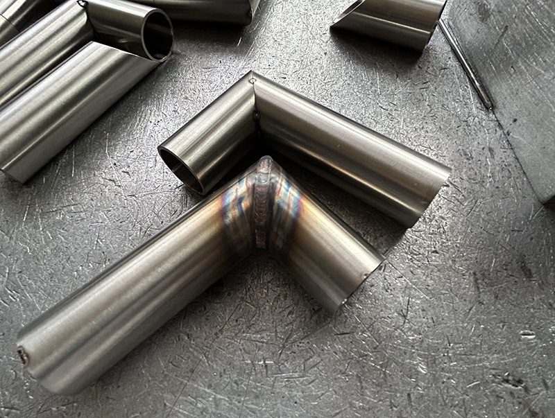
1. Characteristics of the Elbow Geometry
A 90° elbow contains two areas with different welding behaviors:
1. Outer Corner
- Forms a sharp edge on the outside of the bend
- The weld pool tends to spread easily during autogenous welding
➡ Pulse TIG is used in this area to better control the weld pool and maintain bead shape
2. Inner Corner
- Has a much tighter angle
- The weld pool tends to accumulate or collapse inward due to gravity and heat concentration
➡ DC TIG is preferred for more stable, controlled bead formation
Therefore, the recommended approach for this part is a “Pulse for the outer corner + DC for the inner corner and the straight sections.”
2. Fit-Up and Tack Welding
To prevent the joint from opening or cracking due to thermal expansion and weld shrinkage, sufficient tack welds must be applied.
Tack-Welding Requirements
- At least four tack welds, evenly spaced around the joint
→ Ensures stability during welding
→ Prevents weld separation caused by uneven tension - Tack welds must hold the joint tightly with no visible gaps.
Tack-Weld Parameters
- Current: 40 A
- Time: ≤ 0.3 s
- The tack welds should be small and clean to avoid defects such as porosity or excessive heat-affected zones during final welding.
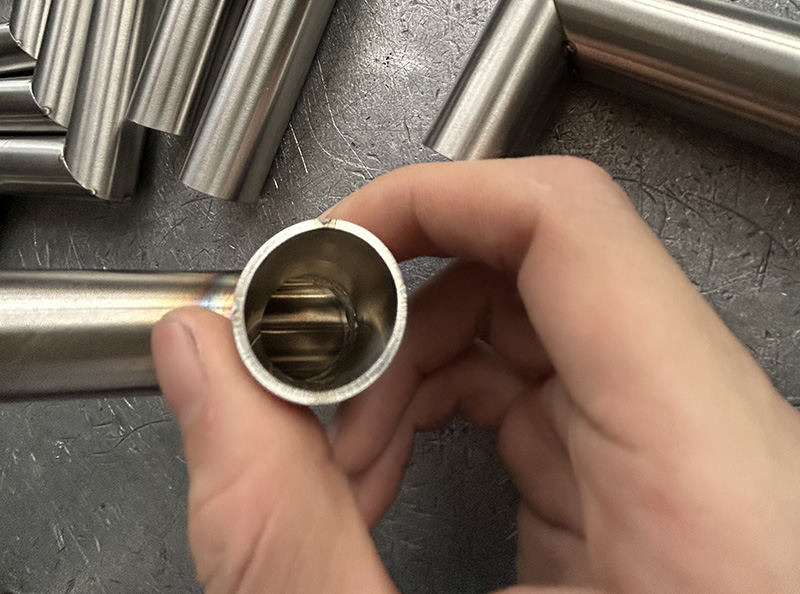
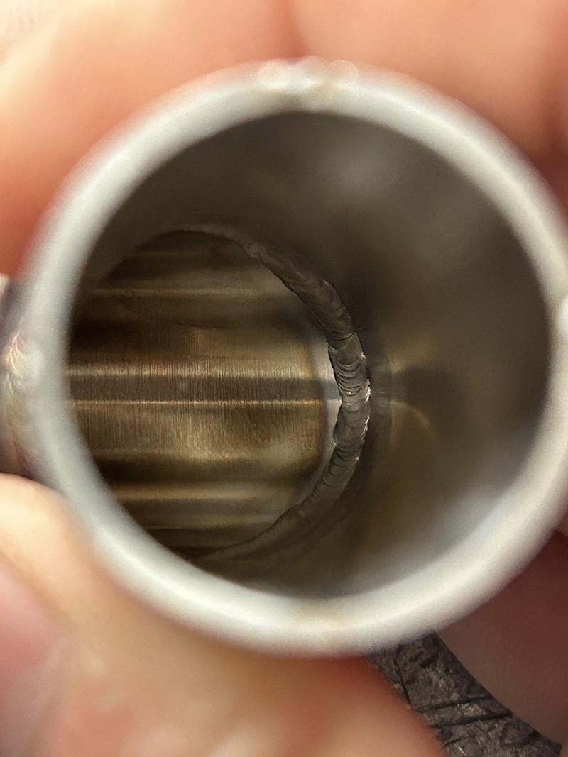
3. Backside Argon Purging (Critical)
Proper backside shielding is essential to prevent oxidation and “sugaring” inside the tube.
- Purge must be maintained from the start of welding until full cooling is complete
4. Welding Sequence and Parameters
Welding Order
- Weld the outer sharp corner first using Pulse TIG
- Then weld the inner corner and the remaining straight sections using DC TIG
This sequence helps prevent the outer corner from deforming, tilting inward, or shrinking as additional heat is applied later.
5. Pulse TIG Welding for the Outer Corner (Outer Edge Only)
The sharp outer corner benefits greatly from pulse mode, which stabilizes the weld pool and helps maintain a consistent internal bead width.
Pulse Parameters
- Peak current (Ip): 68 A
- Base current (Ib): 15 A
- Duty cycle: 20%
- Frequency: 1.4 Hz
6. DC TIG Welding for the Inner Corner and Straight Sections
The inner corner tends to gather excess molten metal, so a smooth and stable DC arc is better suited for this area.
DC Parameters
- Welding current: 29 A